

Pulse-Jet Dust Collector in Cattle Feed Plants: Working Principle, Design, Benefits, Applications, Safety and Maintenance Guide
Introduction
Dust is one of the most common operational challenges in a cattle feed manufacturing plant. Every time maize, soybean meal, bran, oil cake, mineral powder, salt, limestone, vitamins or another ingredient is unloaded, conveyed, ground, mixed, screened or packed, fine particles can become airborne. If this dust is not captured effectively, it may spread throughout the production area, accumulate on machinery, enter electrical panels, affect worker health and create potential fire or combustible-dust hazards.
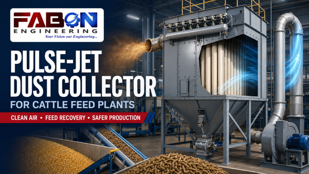
A pulse-jet dust collector is one of the most effective systems used to control fine airborne particles in a modern cattle feed plant. It continuously filters dusty air through fabric bags or cartridges and automatically cleans the filter elements with short pulses of compressed air. This automatic cleaning allows the system to operate for long periods without stopping the production line.
Pulse-jet dust collectors are commonly connected to raw-material receiving hoppers, hammer mills, mixers, bucket elevators, pellet coolers, crumbler machines, vibro screens, finished-product bins and bagging machines. They may be installed as individual collectors for specific machines or as part of a centralized aspiration system serving several dust-generating points.
A properly designed dust-collection system does much more than keep the factory clean. It helps recover valuable feed material, improves product quality, protects mechanical and electrical equipment, reduces housekeeping costs and supports safer working conditions. It can also improve process efficiency by maintaining controlled airflow through grinding, cooling and conveying equipment.
This guide explains the working principle, construction, design, selection, installation, operation, safety and preventive maintenance of pulse-jet dust collectors used in cattle feed plants.
What Is a Pulse-Jet Dust Collector?
A pulse-jet dust collector is an air-pollution-control and material-recovery system that removes suspended solid particles from an air stream. It normally uses multiple cylindrical or envelope-shaped fabric filter bags arranged inside a sealed metal housing.
Dust-laden air enters the collector through an inlet. As the air passes through the filter bags, the fabric traps solid particles while relatively clean air passes to the clean-air chamber. An induced-draft fan then discharges the filtered air through a stack or another approved outlet.
As dust accumulates on the bags, airflow resistance gradually increases. The pulse-jet cleaning system removes this accumulated dust by releasing short bursts of compressed air into the bags. The sudden pulse causes each bag to expand and flex, dislodging the dust layer from its surface. The released material falls into a hopper below the collector and is discharged through a rotary airlock, screw conveyor or sealed collection container.
The word “pulse” refers to the short, high-energy burst of compressed air. The word “jet” refers to the way this air is directed into the filter bag through a blowpipe and nozzle.
Unlike some older bag-filter systems, a pulse-jet collector can clean its bags while filtration continues. This makes it suitable for continuous cattle feed production.
Why Dust Is Generated in a Cattle Feed Plant
A cattle feed plant processes many dry, fragile and powdery ingredients. Each material behaves differently during handling.
Maize and other grains may produce dust during unloading, cleaning and grinding. De-oiled rice bran, wheat bran and soybean meal contain a large proportion of small particles that can become airborne easily. Mineral ingredients such as limestone powder, dicalcium phosphate and salt may create very fine dust. Premixes and micro-ingredients are used in smaller quantities, but their fine particle size makes controlled handling particularly important.
Dust is usually generated at the following stages:
- Unloading raw materials from trucks or bags
- Feeding ingredients into receiving hoppers
- Screening and cleaning grains
- Transferring material between conveyors
- Lifting ingredients through bucket elevators
- Grinding grains in a hammer mill
- Discharging ground material from the mill
- Filling and emptying storage bins
- Batching different ingredients
- Adding micro-ingredients
- Mixing dry feed
- Conditioning mash before pelletizing
- Cooling hot feed pellets
- Crumbling pellets into smaller particles
- Screening finished feed
- Returning fines to the pellet mill
- Weighing and filling bags
- Stitching and handling packed bags
Without extraction, airborne particles settle on floors, roof structures, motors, bearings, lights, cables and control panels. Continuous accumulation can turn a manageable dust problem into a major maintenance and safety concern.
Importance of Dust Control in Feed Manufacturing
Dust control is essential for technical, commercial and safety reasons.
Worker Health and Comfort
Continuous exposure to grain and feed dust can irritate the eyes, skin, nose and respiratory system. Dust may contain grain particles, fungal material, microorganisms, feed additives and mineral ingredients.
A dust collector reduces airborne contamination at its source. It does not eliminate the need for personal protective equipment, workplace monitoring or safe operating procedures, but it provides an important engineering control.
Product Recovery
Much of the dust generated in a feed plant is valuable feed material. If it escapes into the factory, it becomes a production loss and may become contaminated before it can be recovered.
A suitable collector captures the material in a controlled manner. Depending on its origin and condition, it may be returned to the process.
Product Quality
Excessive dust in finished feed bags can lead to customer complaints. A well-controlled cooling and screening section removes loose fines from pellets and helps deliver a cleaner product.
Equipment Protection
Dust can enter motor cooling passages, bearings, sensors, electrical enclosures and control panels. It may cause overheating, inaccurate readings and premature equipment failure.
Housekeeping
A dusty factory requires frequent sweeping and manual cleaning. Traditional dry sweeping may lift settled dust back into the air. Capturing dust at the source reduces housekeeping labour and prevents repeated contamination.
Fire and Explosion Risk Reduction
Many organic feed ingredients can produce combustible dust. A suspended cloud of fine particles can burn rapidly if it encounters a suitable ignition source. Dust accumulation also provides fuel for fires.
Effective extraction, good housekeeping, ignition prevention and appropriate protection systems help reduce these risks.
Professional Plant Appearance
A clean cattle feed plant creates confidence among customers, employees, auditors and business partners. Dust control demonstrates attention to quality and responsible plant management.
Working Principle of a Pulse-Jet Dust Collector
The operation of a pulse-jet collector can be divided into six stages.
Stage 1: Dust Capture
Dust must first be captured close to its source. An extraction hood, enclosed transfer chute or aspiration connection is installed near the dust-generating machine.
The hood should capture airborne particles without removing an excessive quantity of useful feed material. Correct hood positioning often reduces the required airflow and fan power.
Stage 2: Transportation Through Ducts
The dust-laden air moves through a duct network under negative pressure created by a fan. The air velocity must be high enough to keep particles suspended.
If velocity is too low, dust settles inside the duct. If it is too high, power consumption, noise, product loss and abrasion can increase.
Stage 3: Entry into the Collector
Dusty air enters the collector housing. The inlet may direct the air downward or sideways to reduce direct impact on the filter bags. In some designs, larger particles lose momentum and fall directly into the hopper.
A pre-separation chamber or cyclone can be installed before the pulse-jet collector when dust concentration is high.
Stage 4: Filtration
The air passes through the filter fabric. Solid particles remain on the dirty side of the bags, while filtered air enters the clean-air chamber.
At the beginning of operation, the filter fabric captures particles directly. As dust accumulates, a porous layer known as the dust cake forms on the surface. This dust cake can improve fine-particle filtration.
However, an excessively thick layer increases resistance and reduces airflow. Controlled cleaning is therefore necessary.
Stage 5: Pulse-Jet Cleaning
A compressed-air receiver supplies air to diaphragm valves connected to blowpipes. When the controller activates a valve, a short pulse of compressed air travels through the blowpipe and nozzle.
The high-velocity air induces additional surrounding air and directs it into the filter bag. The bag expands rapidly, creating a shock wave that dislodges the accumulated dust cake.
Cleaning can be controlled by:
- A fixed timer
- Differential-pressure readings
- PLC logic
- A combination of time and pressure
Differential-pressure-based cleaning is often more efficient because it operates according to actual filter condition.
Stage 6: Dust Discharge
Dislodged material falls into the hopper. A rotary airlock or screw conveyor removes it continuously or at controlled intervals.
The discharge system must prevent outside air from entering the collector. Excessive air leakage can disturb dust movement, reduce suction at pickup points and increase fan power.
Main Components of a Pulse-Jet Dust Collector
Collector Housing
The housing encloses the filter bags, clean-air chamber and dust hopper. It is generally manufactured from fabricated mild steel. Food-grade or corrosion-resistant applications may require stainless steel.
The housing must withstand the negative pressure created by the fan. Reinforcement is required to prevent panel deformation.
Dirty-Air Inlet
The inlet directs dust-laden air into the collector. Its shape and position influence particle distribution and filter wear.
Poor inlet design can cause high-velocity dust to strike a small group of bags, leading to uneven loading and premature damage.
Filter Bags
Filter bags are the main separation elements. They are manufactured from selected fabric media and supported by metal cages.
The correct filter material depends on:
- Dust characteristics
- Operating temperature
- Moisture
- Chemical exposure
- Required filtration efficiency
- Static-electricity considerations
- Cleaning intensity
Bags must be installed correctly to prevent leakage around their sealing points.
Filter Cages
Wire cages support the bags and prevent them from collapsing under negative pressure. They should have smooth surfaces so that they do not damage the fabric.
Bent, corroded or rough cages can cause premature bag failure.
Tube Sheet
The tube sheet separates the dusty-air chamber from the clean-air chamber. Each filter bag is sealed into an opening in this plate.
Cracks, corrosion or poor bag seating at the tube sheet can allow dusty air to bypass the filter media.
Blowpipes and Nozzles
Blowpipes are positioned above the filter rows. Precisely aligned holes or nozzles direct compressed-air pulses into the centre of each bag.
Incorrect alignment reduces cleaning effectiveness and may cause uneven bag movement.
Compressed-Air Header
The compressed-air header stores the air required for pulsing. It must have adequate capacity and pressure.
The air should be clean and dry. Moisture or oil in the compressed-air supply can damage valves and contaminate filter bags.
Diaphragm Valves
Fast-acting diaphragm valves release compressed air into the blowpipes. Their opening duration is short but powerful.
A leaking or slow valve can cause poor cleaning and excessive compressed-air consumption.
Solenoid Valves
Solenoid valves receive electrical signals from the pulse controller and operate the diaphragm valves.
Pulse Controller
The controller determines the cleaning sequence, pulse duration and interval. Modern collectors may connect to a PLC and HMI for monitoring and alarm functions.
Dust Hopper
The hopper receives dust removed from the bags. Its walls should be steep enough to promote material flow.
Flat areas, internal obstructions or shallow angles can cause bridging and accumulation.
Rotary Airlock Valve
The rotary airlock discharges material while maintaining the collector’s pressure seal. Its rotor contains multiple pockets that carry dust from the hopper to the outlet.
Excessive rotor clearance can cause air leakage. A stopped airlock can lead to hopper overfilling and dust re-entrainment.
Screw Conveyor
Large dust collectors may have several hopper sections. A screw conveyor collects material from each section and transfers it to a single discharge point.
Induced-Draft Fan
The fan creates the negative pressure needed to capture and transport dusty air. It must provide the required airflow at the total resistance of the system.
Installing the fan on the clean-air side reduces erosion of the fan impeller.
Differential-Pressure Gauge
The differential-pressure instrument measures the pressure difference between the dirty-air and clean-air chambers. It is one of the most important indicators of collector performance.
An increasing pressure difference generally suggests dust accumulation or restricted airflow. An abnormally low reading may indicate damaged bags, low airflow or an open bypass.
Inspection Doors
Sealed access doors allow operators to inspect the bags, hopper and cleaning system. Door gaskets must remain airtight during operation.
Types of Pulse-Jet Dust Collectors
Bag-Type Pulse-Jet Collector
This is the most common design for medium and heavy dust loading. Cylindrical fabric bags provide a large filtration area and good dust-holding capacity.
Cartridge-Type Collector
Cartridge collectors use pleated filter elements. They provide a large filtration area in a compact housing and may be useful for fine, dry dust.
However, fibrous feed material can become trapped in the pleats. The suitability of cartridges should be confirmed for the specific dust.
Bin-Vent Filter
A bin-vent filter is mounted directly on a storage bin or silo. It filters displaced air while material enters the bin.
Collected dust falls back into the same bin, eliminating separate dust-return equipment.
Centralized Dust Collector
A centralized system connects multiple machines through a duct network. It can reduce the number of individual collectors but requires careful airflow balancing.
Machine-Mounted Collector
A compact collector can be mounted directly on a mixer, screen, conveyor or bagging machine. This minimizes duct length and may return dust directly to the process.
Cyclone and Pulse-Jet Combination
A cyclone removes the heavier particles before air enters the fabric filter. This reduces dust loading on the bags and can improve system reliability.
Applications in a Cattle Feed Plant
Raw-Material Receiving Hopper
When dry ingredients are tipped into a receiving hopper, displaced air carries dust upward. An extraction hood or enclosed aspiration system captures this dust.
The airflow should be sufficient to contain the cloud without pulling large quantities of raw material into the duct.
Bag-Dumping Station
Operators may manually empty ingredient bags into a hopper. A dust-controlled bag-dumping station typically includes a partially enclosed opening and rear extraction connection.
This configuration pulls dust away from the operator’s breathing zone.
Pre-Cleaner
A grain pre-cleaner removes stones, fibres and oversized contaminants. Movement across screens can generate dust. Aspiration also helps separate lightweight impurities from grain.
Bucket Elevator
Dust can be released at the head and boot sections of bucket elevators. Internal dust accumulation may also create a safety concern.
Aspiration points should be designed without disturbing material flow or reducing elevator performance.
Hammer Mill
The hammer mill is one of the most significant dust sources. Rotating hammers grind grain at high speed, while internal airflow carries fine particles through the screen.
A properly designed aspiration system can:
- Remove heat from the grinding chamber
- Assist material flow through the screen
- Improve grinding capacity
- Reduce internal pressure
- Control dust leakage
- Transport ground material
Too much aspiration can remove excessive product, increase filter loading and consume unnecessary energy. Too little aspiration can reduce mill capacity and cause dust escape.
Batching Bins
Air must leave a bin when material enters. If this displaced air is not filtered, dust may escape through openings. Bin-vent filters or centralized aspiration connections are commonly used.
Ribbon or Paddle Mixer
Dust may be generated while dry ingredients enter the mixer and when the mixer discharges. A vent filter equalizes pressure while retaining feed particles.
The extraction system should not remove lightweight ingredients unevenly, as this could affect formulation accuracy.
Micro-Ingredient Addition
Vitamins, minerals and additives are often fine powders. A controlled dust hood protects the operator and prevents cross-contamination.
Because micro-ingredients are included in precise quantities, extraction must be carefully designed to avoid significant ingredient loss.
Pellet Mill and Conditioner
Steam conditioning adds moisture and heat to mash before pelletization. The area may contain a mixture of warm air, vapour and dust.
Filter equipment must be positioned so condensation does not wet the bags. Moisture management is critical because sticky material can block filter media.
Counterflow Pellet Cooler
Fresh pellets leave the pellet mill hot and relatively soft. A counterflow cooler draws ambient air through the pellet bed.
The exhaust air carries heat, moisture and pellet fines. A cyclone may remove larger fines before the air enters a pulse-jet filter.
Recovered fines can generally be returned to the pelletizing process.
Pellet Crumbler
A crumbler breaks larger pellets into smaller particles. This action creates fines that should be captured and separated.
Vibro Screen and Pellet Grader
Screening separates saleable pellets from fines and oversized material. Enclosing the screen and providing controlled extraction reduces dust release.
Bagging Machine
Dust is generated as feed enters open bags. A local extraction hood around the filling spout captures the displaced dusty air.
The hood should not interfere with bag placement, weighing accuracy or stitching.
Filter-Media Selection
Filter media is not a universal component. The wrong material can lead to poor filtration, high pressure drop or early failure.
Important characteristics include:
Temperature Resistance
Normal cattle feed dust collection usually operates near ambient temperature, but cooler exhaust and conditioner applications may be warmer. The media must tolerate both normal and upset temperatures.
Moisture Resistance
Moisture can cause feed dust to stick to the fabric and block its pores. Filter media should be suitable for expected humidity and condensation risks.
Antistatic Properties
Because cattle feed dust may be combustible, antistatic filter media may be considered as part of the overall hazard-control strategy. Grounding continuity must be maintained.
Surface Finish
A surface treatment or membrane can improve dust release and fine-particle filtration. The correct finish depends on dust characteristics.
Mechanical Strength
Filter bags repeatedly flex during pulse cleaning. They must withstand this mechanical stress while retaining dimensional stability.
Food and Feed Suitability
Where collected material is returned to production, the filter components should be appropriate for feed-manufacturing conditions and should not introduce contamination.
Air-to-Cloth Ratio
Air-to-cloth ratio is an important bag-filter design parameter. It represents the volume of air passing through a unit area of filter media.
It may be expressed as:
Air-to-cloth ratio = Airflow rate ÷ Total filter area
A high air-to-cloth ratio means more air passes through a smaller filter area. This can make the collector compact, but it may increase pressure drop, bag-cleaning frequency and particle penetration.
A lower air-to-cloth ratio provides more filter area, potentially reducing resistance and improving bag life. However, it increases the size and cost of the collector.
The correct ratio depends on:
- Dust type
- Dust concentration
- Particle size
- Moisture
- Filter media
- Cleaning method
- Operating hours
- Required emission performance
Feed dust can be fine, fibrous and sometimes sticky. Conservative design may provide more stable long-term performance than selecting the smallest possible collector.
Airflow and Duct Design
A pulse-jet collector can perform properly only when connected to a well-designed airflow system.
Capture Velocity
Capture velocity is the air speed required near a dust source to draw particles into the hood. It depends on how quickly and in which direction the dust is released.
Enclosing the source allows lower airflow than trying to capture dust from a large open area.
Conveying Velocity
Once dust enters a duct, the air must move fast enough to prevent settlement. The required velocity depends on particle size, shape and density.
Excessively low velocity leads to deposits and blockages. Excessively high velocity increases power use, noise and wear.
Duct Diameter
Duct diameter is selected according to the required airflow and velocity. Improperly sized branches disturb system balance.
Bends and Transitions
Every elbow, reducer and branch creates pressure loss. Long-radius bends and gradual transitions are preferable.
Abrasion is often highest at elbows where particles strike the outer surface. Replaceable wear plates may be used where necessary.
Dampers
Balancing dampers regulate airflow to individual extraction points. Each branch should be tested and adjusted during commissioning.
Leakage
Air leakage through poor joints, open inspection doors or damaged flexible sleeves reduces suction at the machines. All connections should remain sealed.
Fan Selection
The fan must deliver the required air volume against the total static pressure of the complete system.
Total resistance includes:
- Pickup hoods
- Duct friction
- Bends and transitions
- Cyclone pressure loss
- Filter pressure drop
- Dampers
- Stack resistance
- Safety equipment
A fan selected only by motor horsepower may fail to provide the correct operating point.
Important fan considerations include:
- Airflow capacity
- Static pressure
- Fan efficiency
- Motor efficiency
- Impeller design
- Dust concentration
- Temperature
- Noise
- Speed control
- Future expansion
A variable-frequency drive can control fan speed and reduce energy use when full airflow is not required. However, speed must not fall below the level needed to transport dust safely through the duct.
Differential Pressure and Filter Performance
Differential pressure provides a useful indication of filter condition.
Normal Differential Pressure
A stable reading within the designed range generally indicates that the bags are filtering and cleaning correctly.
High Differential Pressure
Possible causes include:
- Heavy dust accumulation
- Insufficient pulse pressure
- Failed diaphragm valves
- Incorrect pulse timing
- Wet or sticky bags
- Excessive airflow
- Undersized filter area
- Blocked clean-air outlet
- Compressed-air supply failure
Low Differential Pressure
Possible causes include:
- Torn or missing filter bags
- Improperly seated bags
- Cracked tube sheet
- Open bypass
- Low fan speed
- Blocked inlet duct
- Incorrect instrument reading
Differential pressure should be monitored as a trend rather than considered only during a breakdown.
Pulse-Cleaning Controls
Pulse cleaning should remove enough dust to maintain airflow without over-cleaning the bags.
Important settings include:
- Pulse duration
- Time between pulses
- Sequence of bag rows
- Compressed-air pressure
- Differential-pressure start point
- Differential-pressure stop point
Excessive cleaning can wear bags, consume compressed air and remove the useful dust cake. Insufficient cleaning causes high pressure drop and reduced suction.
Demand-based cleaning activates according to differential pressure and usually provides better control than a fixed timer alone.
Dust Discharge and Material Recovery
Dust removed from the bags must leave the hopper reliably. A collector cannot operate properly if its discharge section is blocked.
The discharge arrangement may include:
- Rotary airlock
- Screw conveyor
- Slide gate
- Sealed drum
- Fines-return conveyor
- Pneumatic conveying line
If the collected material is returned to feed production, the system should prevent contamination and uncontrolled mixing between formulas.
For example, dust collected from a line producing one cattle feed formulation should not automatically enter another formula without quality approval. Cross-contamination is particularly important when medicated feed or special additives are involved.
Benefits of Pulse-Jet Dust Collectors
Continuous Cleaning
Filter bags are cleaned while the collector remains in operation, supporting continuous production.
High Fine-Dust Collection Efficiency
Fabric filtration can capture much finer particles than a basic cyclone separator.
Lower Material Loss
Recovered feed dust can often be returned to production, improving raw-material utilization.
Cleaner Factory
Source extraction prevents dust from spreading across the building and equipment.
Improved Working Conditions
Reduced airborne dust creates a more comfortable and professional work environment.
Protection of Machinery
Clean surroundings help reduce dust entry into bearings, motors and electrical systems.
Flexible Design
Pulse-jet collectors are available in different sizes and configurations. They can serve one machine or an entire production section.
Automated Operation
The cleaning sequence can be integrated with PLC and HMI controls.
Improved Pellet Quality
Dust extraction from pellet coolers and screens helps remove loose fines from finished pellets.
Reduced Downtime
A properly maintained collector prevents dust-related blockages and can operate continuously for extended periods.
Limitations and Challenges
Pulse-jet collectors also have limitations:
- Filter bags require eventual replacement.
- Compressed air is required for cleaning.
- Wet or sticky dust can block the media.
- Sparks and hot particles may damage the bags.
- Poorly maintained valves reduce performance.
- Incorrect design can lead to high energy consumption.
- Collected material can bridge in the hopper.
- Fire and explosion protection may be necessary.
- Air leakage can disturb process balance.
- Cross-contamination must be managed when dust is recycled.
These challenges can be controlled through proper engineering and preventive maintenance.
Combustible-Dust Safety
Many feed ingredients are organic materials capable of burning. When fine dust is dispersed in air and confined inside equipment, it may present a rapid-combustion or explosion hazard.
A dust explosion generally requires:
- Combustible dust
- Oxygen
- An ignition source
- Dust dispersion
- Confinement
A dust collector naturally contains concentrated dust, air and confinement. Safety measures must therefore be considered during design.
Potential ignition sources include:
- Sparks from metal entering the hammer mill
- Overheated bearings
- Belt friction
- Static discharge
- Electrical faults
- Welding and cutting work
- Hot particles
- Smoking
- Mechanical impact
- Smouldering material
Possible controls include:
- Magnetic separators
- Stone traps
- Bearing-temperature sensors
- Belt-alignment monitoring
- Spark detection
- Automatic extinguishing
- Grounding and bonding
- Antistatic filter media
- Explosion venting
- Explosion suppression
- Isolation valves or barriers
- Suitable electrical equipment
- Emergency shutdown interlocks
- Strict housekeeping
- Hot-work permits
The required protection should be determined through a formal dust-hazard assessment by qualified professionals.
Grounding and Static Control
Dry particles moving through ducts can generate static electricity. All conductive parts of the dust-collection system should be bonded and grounded.
This includes:
- Ducts
- Collector housing
- Fan
- Rotary airlock
- Screw conveyor
- Flexible connections
- Storage bins
- Supporting structure
Flexible hoses and sleeves should not interrupt electrical continuity. Grounding connections should be inspected periodically.
Preventing Condensation
Moisture is a major concern in pulse-jet filtration. If humid or warm air cools below its condensation point, water may form inside ducts and on filter bags.
Wet feed dust can create a sticky layer that is difficult to remove with compressed-air pulses. It may also promote microbial activity and corrosion.
Condensation can be reduced through:
- Proper placement of the collector
- Insulated ducts
- Temperature monitoring
- Avoidance of cold air leakage
- Adequate system warm-up
- Controlled process moisture
- Shorter duct runs
- Correct ventilation
- Suitable filter media
Cooler and conditioner exhaust systems need special attention because they may contain warm, moisture-laden air.
Installation Guidelines
The collector should be installed on a strong, level foundation or support structure. Enough clearance must be provided for maintenance.
Important installation requirements include:
- Adequate structural support
- Correct inlet and outlet orientation
- Airtight flange connections
- Independent duct supports
- Access for bag removal
- Clearance for airlock maintenance
- Safe access platforms
- Weather protection for outdoor units
- Proper fan alignment
- Correct grounding
- Compressed-air drainage
- Inspection lighting where appropriate
- Safe discharge of explosion vents, if installed
The duct’s weight should not be carried by the collector inlet. Excessive load can distort the housing and create leakage.
Commissioning Procedure
Commissioning should begin with a complete inspection before raw material enters the plant.
Mechanical Inspection
Check:
- Bag and cage installation
- Tube-sheet sealing
- Access-door gaskets
- Rotary-airlock direction
- Screw-conveyor direction
- Fan rotation
- Drive guards
- Damper position
- Structural supports
- Grounding
- Duct connections
Compressed-Air Test
Verify:
- Supply pressure
- Air quality
- Header drainage
- Pulse sequence
- Valve operation
- Blowpipe alignment
- Pulse duration
Electrical Test
Check:
- Motor protection
- Emergency stops
- Interlocks
- Differential-pressure transmitter
- Hopper-level sensor
- Temperature sensor
- PLC and HMI indications
No-Load Operation
Run the fan and inspect vibration, current, noise and leakage. Measure airflow or pressure at important branches.
Load Trial
Introduce material gradually and observe:
- Dust capture at every point
- Filter pressure drop
- Hopper discharge
- Airlock operation
- Fan current
- Pulse-cleaning frequency
- Exhaust appearance
- Dust leakage
- Material recovery
The final settings should be recorded for future comparison.
Operating Sequence
A typical startup sequence is:
- Confirm that the dust hopper is empty.
- Start the rotary airlock and screw conveyor.
- Start the compressed-air system.
- Activate the pulse controller.
- Start the dust-collection fan.
- Confirm suction at the machines.
- Start downstream process equipment.
- Start upstream feeding equipment.
The dust collector should normally start before dust-generating machines.
A typical shutdown sequence reverses the process. After stopping material feed, the fan and pulse-cleaning system may continue briefly to clear the ducts and bags. The correct timing depends on the system design.
Preventive Maintenance Schedule
Daily Inspection
Operators should check:
- Differential pressure
- Compressed-air pressure
- Visible emissions
- Dust leakage
- Fan noise
- Motor current
- Airlock operation
- Hopper level
- Pulse-valve sound
- Dust accumulation
- Alarm status
Weekly Inspection
Maintenance personnel should inspect:
- Door seals
- Flexible sleeves
- Solenoid valves
- Diaphragm valves
- Blowpipes
- Fan belts
- Bearings
- Duct joints
- Airlock seals
- Grounding connections
- Hopper walls
Monthly Inspection
Check:
- Filter-bag condition
- Cage wear
- Tube-sheet sealing
- Fan impeller
- Screw conveyor
- Differential-pressure tubes
- Instrument calibration
- Structural supports
- Compressed-air leaks
- Safety devices
Periodic Shutdown Maintenance
During planned shutdowns:
- Isolate all energy sources.
- Follow lockout procedures.
- Clean internal areas safely.
- Replace damaged bags.
- Repair corroded or worn sections.
- Check explosion-protection equipment.
- Inspect the complete duct network.
- Test interlocks.
- Review maintenance records.
Entry into a collector may involve confined-space and combustible-dust hazards. Only trained personnel should perform internal work under an approved safety procedure.
Filter-Bag Replacement
Filter bags should be replaced when they are torn, blinded, chemically damaged, worn or unable to maintain the required performance.
Before replacement:
- Shut down and isolate the collector.
- Allow dust to settle.
- Follow safe-entry procedures.
- Wear appropriate protective equipment.
- Prevent contaminated dust from spreading.
During installation:
- Inspect cages for sharp edges.
- Clean the tube-sheet openings.
- Seat each bag correctly.
- Maintain the manufacturer’s orientation.
- Avoid folding or damaging the fabric.
- Verify seals before restarting.
When many bags have reached the end of their service life, replacing the complete set may provide more balanced performance than replacing a few bags repeatedly.
Common Problems and Troubleshooting
Dust Escaping from Pickup Points
Possible causes:
- Insufficient airflow
- Poor hood design
- Blocked duct
- Closed damper
- Fan operating in the wrong direction
- Slipping drive belt
- High filter pressure drop
- Air leakage elsewhere
Corrective action should begin with airflow and pressure measurements.
Visible Dust at the Clean-Air Outlet
Possible causes:
- Torn bags
- Bags installed incorrectly
- Damaged tube sheet
- Failed seals
- Incorrect filter media
- Excessive airflow
- Open bypass
A bag-leak-detection inspection can help identify the damaged row.
High Differential Pressure
Possible causes:
- Bags not cleaning
- Low compressed-air pressure
- Failed pulse valve
- Wet dust
- Excessive air volume
- Collector undersized
- Hopper overfilled
- Incorrect pulse settings
Low Differential Pressure
Possible causes:
- Damaged bags
- Insufficient fan speed
- Blocked inlet duct
- Open access door
- Instrument fault
- Incorrect damper position
Dust Not Discharging
Possible causes:
- Stopped rotary valve
- Broken coupling
- Hopper bridging
- High moisture
- Foreign object
- Screw-conveyor failure
- Overfilled collection container
Frequent Filter-Bag Damage
Possible causes:
- Abrasive inlet flow
- Cages with sharp edges
- Excessive pulse pressure
- High temperature
- Chemical attack
- Condensation
- Incorrect bag installation
- Sparks or hot particles
High Compressed-Air Consumption
Possible causes:
- Leaking diaphragm valves
- Excessive cleaning frequency
- Damaged air lines
- Incorrect controller settings
- Unnecessary continuous pulsing
Fan Vibration
Possible causes:
- Dust buildup on the impeller
- Bearing failure
- Misalignment
- Foundation looseness
- Impeller wear
- Foreign material
- Unbalanced rotor
Material Buildup in Ducts
Possible causes:
- Low conveying velocity
- Incorrect duct diameter
- Excessive horizontal runs
- Moisture
- Poor branch design
- Air leakage
- Sudden expansion in duct size
Energy-Efficiency Opportunities
Dust collection can consume significant electrical energy, mainly through the fan and compressed-air system.
Energy use can be reduced by:
- Correctly sizing the fan
- Minimizing duct length
- Using smooth-radius bends
- Sealing air leaks
- Maintaining clean filters
- Controlling fan speed through a VFD
- Using differential-pressure-based cleaning
- Repairing compressed-air leaks
- Closing unused extraction branches
- Positioning hoods close to dust sources
- Avoiding unnecessary airflow
Energy savings should never reduce the airflow below safe capture and conveying requirements.
Selecting the Right Pulse-Jet Dust Collector
Before selecting a collector, the plant owner should provide the supplier with complete process information.
Important details include:
- Cattle feed plant capacity
- Mash or pellet-feed production
- Raw materials used
- Number of dust-extraction points
- Required airflow at each point
- Dust concentration
- Particle-size distribution
- Moisture and temperature
- Operating hours per day
- Required outlet-air quality
- Available compressed-air pressure
- Indoor or outdoor installation
- Dust-recycling plan
- Cross-contamination requirements
- Fire and explosion hazards
- Future plant expansion
- Space available
- Level of automation
The collector should not be selected only according to tonnes of feed produced per hour. A two-tonne-per-hour plant with many open transfer points may require more extraction air than a larger but highly enclosed plant.
Centralized Versus Individual Dust Collection
Centralized System
A central collector serves several production machines.
Advantages include:
- One main filter unit
- Centralized maintenance
- Simplified exhaust arrangement
- Potentially lower total equipment count
Limitations include:
- Complex duct balancing
- Longer duct runs
- Possible cross-contamination
- Entire system affected by one failure
- Higher central fan capacity
Individual Collectors
Small collectors are installed close to specific machines.
Advantages include:
- Shorter ducts
- Easier material return
- Reduced cross-contamination
- Independent operation
- Easier future expansion
Limitations include:
- More motors and control devices
- Multiple maintenance points
- Higher equipment count
Many plants use a combination of both arrangements.
Automation and Smart Monitoring
Modern pulse-jet collectors can be fully integrated with the feed plant’s PLC and HMI.
Useful monitored parameters include:
- Fan running status
- Fan motor current
- Differential pressure
- Compressed-air pressure
- Hopper level
- Rotary-airlock status
- Screw-conveyor overload
- Filter inlet temperature
- Pulse-valve operation
- Spark alarm
- Explosion-protection status
- Vibration
- Damper position
Interlocks may stop the hammer mill, cooler or bagging machine if the dust collector fails. This prevents the production line from continuing without adequate extraction.
Historical data can identify gradual performance changes. For example, a slow increase in differential pressure over several weeks may indicate bag blinding or inadequate cleaning.
Quality-Control Considerations
Dust collection should support feed quality rather than disturb it.
Important quality considerations include:
- Preventing cross-contamination between formulas
- Avoiding loss of micro-ingredients
- Protecting collected material from moisture
- Preventing foreign-material entry
- Maintaining hygienic hopper conditions
- Recording dust-recycle quantities
- Separating nonconforming dust
- Cleaning collectors during formulation changes
- Preventing lubricant contamination
- Using suitable contact materials
Collected dust should be reused only under the plant’s quality-control procedure.
Commercial Benefits
The financial return from dust collection comes from several areas:
- Recovery of sellable feed material
- Reduced manual cleaning
- Lower equipment-maintenance costs
- Improved worker productivity
- Reduced production interruptions
- Better product presentation
- Lower pellet-fines complaints
- Improved plant reliability
- Reduced risk of major dust-related incidents
- Stronger customer confidence
A dust collector should therefore be evaluated according to its lifecycle value, not only its initial purchase price.
Frequently Asked Questions
Is a pulse-jet dust collector required in every cattle feed plant?
The exact arrangement varies, but effective dust control is generally necessary wherever feed ingredients are received, ground, mixed, cooled, screened or packed.
What is the difference between a cyclone and a pulse-jet collector?
A cyclone uses centrifugal force and is effective for larger particles. A pulse-jet collector uses filter media and captures much finer dust. They are often used together.
Can the collector operate continuously?
Yes. Pulse cleaning allows the filter bags to be cleaned while filtration continues.
Can collected feed dust be reused?
Clean dust can often be returned to production, subject to quality-control, hygiene and formulation requirements.
Why are filter bags getting blocked?
Common causes include moisture, condensation, insufficient pulse pressure, incorrect media, excessive dust loading and oil contamination in compressed air.
Why is compressed air required?
Compressed air produces the short cleaning pulses that remove accumulated dust from the filter bags.
How frequently should bags be changed?
There is no fixed interval for every plant. Bag life depends on dust type, operating hours, moisture, temperature, pulse settings, media quality and maintenance.
Should the fan be before or after the collector?
A fan on the clean-air side is often preferred because it experiences less dust-related wear. The final arrangement depends on the process design.
Can filtered air be returned to the production building?
Air recirculation requires careful engineering evaluation of filtration performance, dust hazards, hygiene, temperature and regulatory requirements.
What causes excessive pressure drop?
Common causes include dirty bags, failed pulse cleaning, wet dust, excessive airflow and undersized filter area.
Does the dust collector affect hammer-mill performance?
Yes. Proper aspiration can assist material movement, reduce heat and improve grinding stability. Incorrect airflow can reduce performance or remove excessive product.
Can one collector serve the entire plant?
It is possible, but the network must be carefully designed and balanced. Cross-contamination, duct length and operational flexibility must also be considered.
Conclusion
A pulse-jet dust collector is an essential supporting system in a modern cattle feed plant. It removes fine airborne particles generated during unloading, grinding, mixing, conveying, cooling, screening and packing.
Its operating principle is simple but highly effective. Dusty air passes through fabric filter bags, solid particles remain on the filter surface and clean air exits the collector. Short pulses of compressed air automatically remove the accumulated dust, allowing continuous filtration.
The effectiveness of the collector depends on much more than the number of filter bags. Hoods, ducts, fan capacity, air-to-cloth ratio, filter media, pulse-cleaning controls, hopper design and discharge equipment must be engineered as one complete system.
Correct dust control provides measurable benefits. It recovers valuable feed material, reduces housekeeping, protects machinery, improves working conditions and contributes to cleaner finished products. It can also improve hammer-mill aspiration, pellet-cooler performance and overall plant reliability.
At the same time, cattle feed dust should be treated as potentially combustible. Grounding, spark prevention, bearing monitoring, housekeeping, explosion protection and safe maintenance procedures must be included in the plant’s risk-management programme.
Plant owners should plan dust collection during the initial design of a cattle feed factory. Installing properly sized extraction points, ducts and collectors from the beginning is generally more effective than attempting to control dust after the complete production line has been installed.
A high-quality pulse-jet dust collector is not simply an accessory attached to the plant. It is an important part of the manufacturing process. When designed, installed and maintained correctly, it helps a cattle feed plant operate more cleanly, safely, efficiently and profitably for many years.